NFPA 70E 130.4(D)(a) Shock Protection Approach Boundaries.

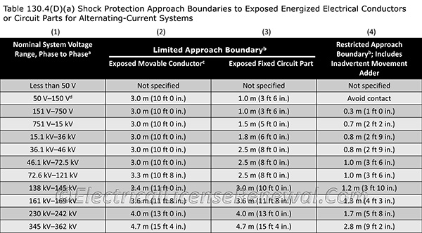
Table 130.4(D)(a) in the NFPA 70E provides shock protection approach boundaries to exposed energized electrical conductors or circuit parts for alternating-current systems.
On the left side of the table is the nominal system voltage range (phase to phase) for the equipment being worked on. On the right side of the table is the restricted approach boundary. In the middle of the table is the limited approach boundary based on one of the two conditions:
- The presence of an exposed movable conductor (such as an overhead conductor)
- The presence of an exposed, fixed in place circuit part (such as a circuit breaker)
Example: A 120/208-volt three phase AC panelboard would operate at 208 volts when measured phase to phase. This results in using the 151 V–750 V row in the table.
In the example, the limited approach boundary for an exposed fixed circuit part is 3 foot, 6 inches. The restricted approach boundary is 1 foot.
Refer to the image of Table130.4(D)(a) to answer the question below.