Checking the Architectural Pages for Rated Walls and Assemblies.

The Architectural pages of a plan set will generally show floor plans that contain any required fire resistive rating designs for walls, and horizontal assemblies (fire-resistance-rated floor/ceiling assemblies, and the ceiling membrane of a roof/ceiling assembly). Knowing where the fire rated floors, walls, or ceilings are in a building helps the electrician to know which floors, walls, or ceilings require special attention when making penetrations or installing boxes and enclosures.
When a rated assembly is shown on the plans, there will then be a design number for that wall, floor, or ceiling assembly. Underwriters Laboratories (UL) tests rated assembly designs to ensure that they function as intended and provide the number of hours of protection specified in the design.
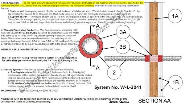
When penetrating a rated wall, floor, or ceiling assembly design, be careful to follow the exact requirements set forth in the through penetration firestopping design specified in the plans (see image). Using a different sealant or raceway type will not align with the tested design specified in the plans and the required fire rated assembly will be compromised.
When a firestopping product manufacturer submits their product to UL for testing, they also include a schematic that dictates exactly how the wall is to be constructed, the number of layers of sheetrock per side, the type of insulation (if any) to be used in the wall cavity, the manufacturer brand of firestopping materials to be used, the manufacturer brand of cable or raceway to be installed, the size raceway or cable to be used, and the like. UL tests the rated assembly exactly as requested by the firestopping product manufacturer using the materials specified. If the assembly passes all UL tests, the assembly is then published as a membrane or through penetration firestop system. If the electrician changes anything from the approved specified design in the field, the change makes the intended design null and void and places responsibility on the electrician in the event that the fire wall, floor, or ceiling doesn’t perform as intended during a fire.
NEC Section 300.21 states the following:
NEC 300.21 Spread of Fire or Products of Combustion. Electrical installations in hollow spaces, vertical shafts, and ventilation or air-handling ducts shall be made so that the possible spread of fire or products of combustion will not be substantially increased. Openings around electrical penetrations into or through fire-resistant-rated walls, partitions, floors, or ceilings shall be firestopped using approved methods to maintain the fire resistance rating.
Informational Note: Directories of electrical construction materials published by qualified testing laboratories contain many listing installation restrictions necessary to maintain the fire resistive rating of assemblies where penetrations or openings are made. Building codes also contain restrictions on membrane penetrations on opposite sides of a fire-resistance-rated wall assembly. An example is the 600-mm (24-in.) minimum horizontal separation that usually applies between boxes installed on opposite sides of the wall. Assistance in complying with 300.21 can be found in building codes, fire resistance directories, and product listings.